Application of electron tomography for comprehensive determination of III-V interface properties
Most modern III-V heterostructure devices require a high level of control over the quality of their interface structures due to their large impact on many physical properties like, for example, the electron mobility in quantum wells or the tunneling behavior of sophisticated heterostructures like quantum cascade lasers. Therefore, a comprehensive interface characterization is necessary to allow the development of novel III-V compound semiconductor devices. In general, heterostructure interfaces are characterized by two fundamental properties: the physical roughness and the chemical intermixing. These properties are typically described by the root mean square (RMS) value of the interface roughness and the lateral and vertical correlation lengths as well as the chemical width of the interface.
Unfortunately, experimental tools to measure these quantities in the case of buried interfaces are fairly limited. X-ray scattering methods are able to deliver detailed information about surfaces and interfaces on large scales, and, complementary, spatially resolved methods like scanning probe microscopy are used to observe local variations providing, however, two-dimension- al (2D) images. Conventional transmission electron microscopy (TEM) in combination with the site-specific focused ion-beam (FIB) sample preparation allows to investigate interfaces in cross-sectional samples down to the atomic level. TEM micrographs are projections of samples with a thickness of up to several nanometers that make it typically difficult to distinguish between the physical roughness and the chemical width without further information.
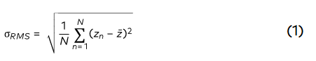 N is the number of pixels, zn the height value
of the n-th pixel and the average height.
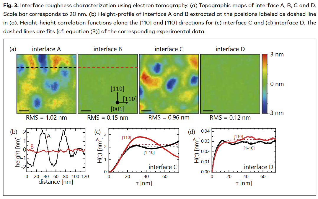
RMS values have been determined for each
interface over the whole (120 nm x 120 nm)
area of the topographic maps with the
result of 1.02 nm and 0.96 nm for the
inverted and 0.15 nm and 0.12 nm for the normal
interfaces, respectively. In agreement with
the topographic maps, the RMS values are
N is the number of pixels, zn the height value
of the n-th pixel and the average height.
RMS values have been determined for each
interface over the whole (120 nm x 120 nm)
area of the topographic maps with the
result of 1.02 nm and 0.96 nm for the
inverted and 0.15 nm and 0.12 nm for the normal
interfaces, respectively. In agreement with
the topographic maps, the RMS values are
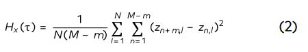 where m = τ/Δx , Δx is the discrete sampling
interval (pixel distance), M and N are the
number of pixels in x-direction and the
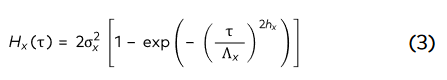
perpendicular direction, respectively. The HHCF
can be phenomenologically described by:
where m = τ/Δx , Δx is the discrete sampling
interval (pixel distance), M and N are the
number of pixels in x-direction and the
perpendicular direction, respectively. The HHCF
can be phenomenologically described by: